Colors for Architect Drawings Autocad
How to Organize Your AutoCAD Layers for Buildings

Without a plan for how to organize your AutoCAD layers, CAD drawings can get messy quick. Luckily, the United States National CAD Standard (NCS) has put together guidelines for how layers should be organized for the architecture and engineering (A&E) industry. The bad news is that they also tack on a hefty fee to acquire them. A student license for the fifth version 5 of the standard released in 2011 is running for $100.00.The good news is that I'm here to share what I know for free!
Layer Standards in the A&E Industry
Naming layers
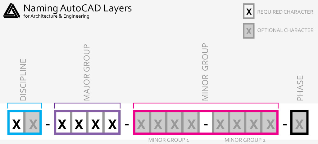
There are four data fields as a CAD standard when creating AutoCAD layer names: discipline , major group , minor groups , and phase.
Example:
A – WALL – FULL – DIMS –N
Discipline: Architecture
Major Group: Wall
Minor Group 1: Full (height wall)
Minor Group 2: Dimensions
Phase: New construction
Discipline
Discipline defines what kind of subject matter the layer contains. The first character is predetermined by the below list. The second character is optional and can be used to further define the discipline.
Discipline Designators
G – General
H – Hazardous Materials
V – Survey / Mapping
B – Geotechnical
W – Civil Works
C – Civil
L – Landscape
S – Structural
A – Architectural
I – Interiors
Q – Equipment
F – Fire Protection
P – Plumbing
D – Process
M – Mechanical
E – Electrical
T – Telecommunications
R – Resource
X – Other Disciplines
Z – Contractor / Shop Drawings
O – Operations
Major Group
The major group defines what over-arching building system the layer falls into. This field is required and it's four characters are predetermined. Some of the most common major group indicators have been listed below but there are many. If what you need doesn't seem to fit into any of these major groups, send a tweet to @designerhacks
and we'll find one for you.
ANNO- Annotation
BEAM – Beam
BLDG – Buildings
BNDY – Boundary
BRDG – Bridge
CLNG – Ceiling
CODE – Code compliance plan
COLS – Column
CURB – Curb
DOOR – Door
ELEV – Elevation
EQPM – Equipment
FLOR – Floor
FNDN – Foundation
FURN – Furniture
GRID – Grid
GLAZ – Glazing
PLNT – Plantings and Landscape
PRKG – Parking
PROP – Property
ROAD – Roadways
SECT – Section
SITE – Site Improvements
TOPO – Topography
WALL – Wall
Minor Groups
Minor groups are optional and are intended to help you further define what is contained within each layer. Per the standard, you're permitted to use what ever names you deem necessary to help define what's on the layer. Just keep in mind that if you decide to make your own you only have two minor groups at four characters each to use.
Phase
Phase defines what construction status the items on your AutoCAD layers have. This is an optional single character that is predetermined in the list below.
N – New work
E – Existing to remain
D – Existing to demolish
F – Future work
T – Temporary work
M – Items to be moved
X – Not in contract
1-9 – Phase numbers
General Tips When Creating AutoCAD Layers
I'll get more into how to really refine your AutoCAD layers later but for now follow these tips to ensure you're on the right track.
- Keep all of your major groups the same color. When you're searching around a drawing it can be insanely difficult to know what's what if there's no order to the way things are colored.
- When defining your layer colors use the index colors.The colors you're using to designate layers are meant to be symbolic. When you print, you're not going to want to see yellow, pink, or blue lines. You can use your plot styles to have the index color to define lineweight instead of color.
- Use the default lineweight for all of your layers. To get varying line weights it's best to set-up plot styles for each of your index colors. This way you can ensure that no matter if you're printing at 8.5×11 or at 24×36 your drawing reads well.
- Create a NPLT (No plot) layer.Sometimes you'll want to keep information in your drawing for your reference but won't want it to print. Create a layer that won't print.
Have questions regarding AutoCAD layers for A&E? Feel free to leave a comment below or tweet us @designerhacks!
Source: https://designerhacks.com/organize-autocad-layers-buildings/
0 Response to "Colors for Architect Drawings Autocad"
ارسال یک نظر